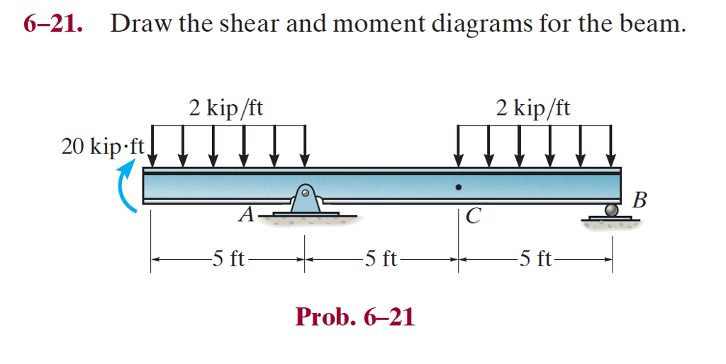

- DRAW THE SHEAR AND MOMENT DIAGRAMS FOR THE BEAM HOW TO
- DRAW THE SHEAR AND MOMENT DIAGRAMS FOR THE BEAM FREE
(ii) A pin joint does not alternate the variation of shear force. (i) The bending moment diagram is zero when passing through a pin joint.
DRAW THE SHEAR AND MOMENT DIAGRAMS FOR THE BEAM HOW TO
Plot Shear and Moment Diagrams The functions for V and M for both beam sections can be plotted to give the shear and moment over the length of the beam. The free-body diagram of the beams right segment sectioned through an arbitrary point shown in Fig.a will be used to write the shear and moment equations of. Shear/Moment diagrams are graphical representations of the internal shear force and bending moment along the whole beam. This video explains how to draw shear force diagram and bending moment diagram with easy steps for a cantilever beam loaded with a concentrated load. Plot the moment and shear equations developed in step 3. The following are observations from the above shear force and bending moment diagrams: Cut the beam (one cut for each beam segment), draw a FBD, and solve for the unknown M and V at the cut in terms of x. On the basis of the calculations in Step 4 and the discussion before Step 1, the shear force and bending moment diagrams are drawn below. Step 5: Draw shear force and bending moment diagrams. Strength of materials deals with this drawing of shear force and bending moment diagram for statically de. The selection of suitable method depends on the degree of indeterminacy of the beam. Thus:įollowing the sign convention, the moment at D is defined as negative. Answer (1 of 8): There are various methods of drawing shear force and bending moment diagram for a beam.

DRAW THE SHEAR AND MOMENT DIAGRAMS FOR THE BEAM FREE
The section at D is a free end subjected to a concentrated moment. Calculate reaction draw shear force diagram find location of V0 calculate maximum moment, and draw the moment diagram. Table 4.2 Common features of shear and bending moment diagramsīending moment M \frac( \downarrow) An abrupt change of shear force occurs at C due to the concentrated support reaction. The shear force and the bending moment are, respectively, linear and parabolic between C and D. From Table 4.2 and Example 4.9, we know that the shear force is constant and the bending moment varies linearly from A to C since there is no external load applied within this range.


 0 kommentar(er)
